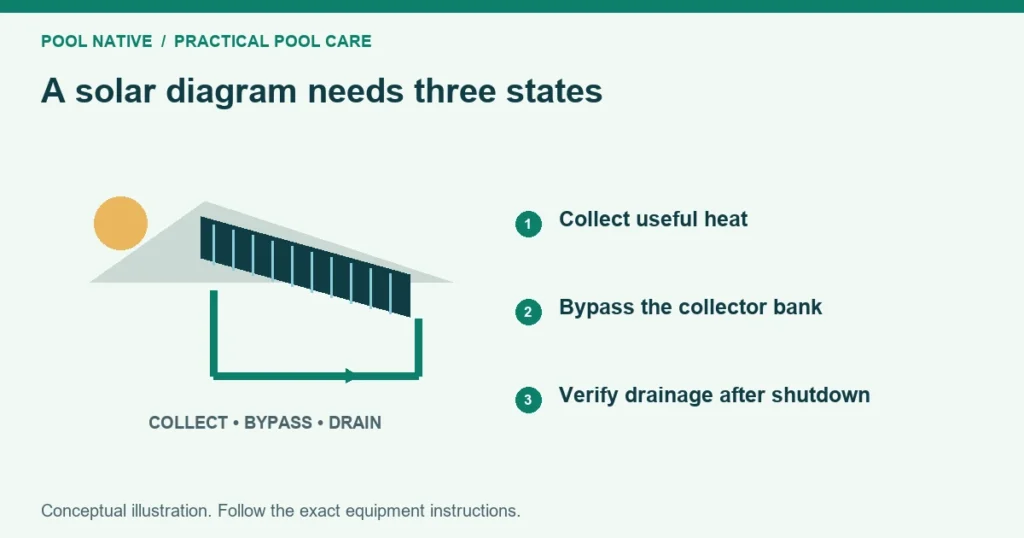
A solar pool heater plumbing diagram should explain three states: collecting heat, bypassing the collectors and draining after shutdown. The same pipes can behave differently in each state. A diagram that shows only the heating arrows leaves important questions unanswered.
The conceptual layout below shows a common filtered pool water system. It is an explanation for an installer discussion, not a construction drawing. Exact valves, pipe sizes, sensor locations and drainage provisions must match the selected equipment and site.
Read the solar pool heater plumbing diagram
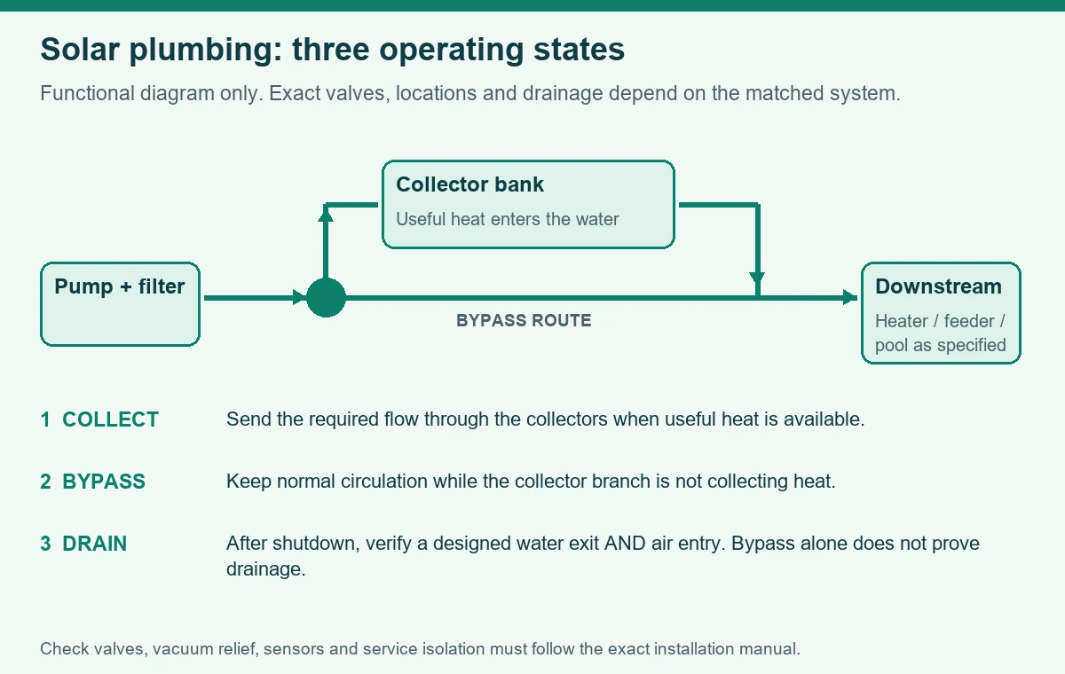
Follow the ordinary circulation route first: pool, pump, filter and return to the pool. The solar branch takes filtered water through the collectors and brings it back to the return route. A bypass connection lets ordinary circulation continue when solar collection is not selected.
In the Heliocol arrangement described by the cited manual, the solar connection is after the filter and before the remaining heater or chemical feeder equipment. A check valve at the filter outlet prevents collector drainage from flowing backward through the filter. Other approved system designs must be checked against their own documentation.
The drawing groups components by function. It does not show every isolation valve, fitting or required separation. Never infer an exact installation dimension from the spacing in an explanatory graphic.
State one: solar heating selected
When heating is wanted and usable solar energy is available, the diverter sends the required flow through the collectors. The warmed water returns to the main circulation route. Depending on the approved design, some water may also use the bypass path.
The collector inlet and outlet arrangement must match the manufacturer’s layout. Panels in a bank need suitable distribution rather than simply being connected in whatever order uses the least pipe. A larger bank can require a different feed or balancing arrangement.
Pump operation must provide the required flow through the solar branch. A total circulation measurement taken before the split cannot establish that branch flow. The pool flow measurement guide explains how to document the measurement location and operating mode.
Do not reduce the flow just to make the solar return feel hotter. A warm trickle can carry less heat than a larger, slightly warmed stream. The solar system operating guide gives a calculated example of that distinction.
State two: collectors bypassed
When solar heat is unavailable or no longer wanted, the controls can select the ordinary return route. Water does not need to pass through the array to maintain normal circulation. This helps avoid unwanted heat exchange through cool collectors.
Bypass does not necessarily mean the collector circuit is completely isolated. Some solar diverters intentionally permit drainage through a small internal route or another designed path. A valve that looks closed can therefore behave differently from a positive isolation valve.
That distinction matters when investigating a leak. Solar OFF on the controller is not permission to loosen a union or open a collector connection. Service isolation must also account for water returning through another line and any static pressure.
Keep the normal bypass position separate from the documented service isolation arrangement. The equipment pad labeling guide shows how to record confirmed positions and purposes. Do not mark a valve “safe to open” merely because it is in a bypass setting.
State three: pump off and drainage
Once the pump stops, water may need to drain from the collectors and exposed piping. The system needs both a route for water to leave and a route for air to enter. Missing either can prevent complete drainage.
A vacuum relief valve admits air when the pressure conditions call for it. It does not pump water out. It cannot drain a low pocket whose only exit rises above the trapped water.
Check valve direction is important because reverse flow is sometimes unwanted and sometimes part of the intended drainage route. The valve protecting the filter has a specific job. Adding extra check valves without reviewing drainage can trap water elsewhere.
The installed diverter design matters too. Replacing a solar valve with a similar looking valve that seals differently can change the drain path. Ask the installer to identify the required internal drainage provision instead of choosing by pipe diameter alone.
Where the vacuum relief valve belongs
Its purpose is to admit air for drainage without drawing air into normal water flow. That requires an appropriate location and pressure condition for the specific system. A generic “put it at the highest point” instruction is incomplete.
The cited Heliocol manual describes permitted arrangements at the collectors or on the feed line. Its detailed instructions must be reconciled with the actual equipment elevation and layout. Have the manufacturer or installer resolve unclear dimensions rather than averaging conflicting instructions.
Persistent return bubbles only while solar is operating can be relevant to this assessment. A vacuum relief valve may admit air when operating pressure is insufficient, or air may enter elsewhere. Do not cap or remove the valve as a workaround.
Brief startup air as the system fills is a different observation from continuous bubbling. Record duration, pump state and whether the pump basket contains air. Those details help the technician separate filling behavior from an ongoing air entry problem.
Parallel banks and balanced paths
Many pool collector arrays use parallel flow through panels or banks. That helps distribute the water without forcing all of it through one long successive path. The exact manufacturer can permit particular combinations or bank limits.
A balanced layout aims to give each branch suitable flow. A short easy route can take a disproportionate share while a remote bank receives too little. Simply adding more panels does not ensure the new area is usefully supplied.
Reverse return arrangements or specified balancing provisions can address that problem. The installer should show where the banks split and rejoin and how their flow is verified. Do not copy a manifold layout from a different panel model.
Roof obstacles also affect drainage. Pipes crossing a ridge or dipping around an obstruction can create trapped sections. Draw changes in height on the installation sketch, not just lines viewed from above.
Keep the control path separate from the water path
A solar controller uses temperature information and the selected heating mode to decide when to operate the diverter or pump. A sensor representing pool water must not accidentally read a warmed return as though it were the whole pool. Sensor installation follows the controller’s instructions.
Draw sensor and actuator connections in a different style from water pipes. Label the actual sensor locations and controlled valve. A diagram should not make a low voltage control wire look like a water bypass.
If a backup heater is present, identify the control priority and flow requirements. The powered heater bypass explanation covers a different component that may exist on the same pad. Do not confuse its thermostat bypass mode with either solar plumbing branch.
What to ask the installer to add
- Exact collector models, bank sizes and usable area.
- Pipe material, nominal size and permitted joint system.
- Direction and purpose of every check valve.
- Normal heating, bypass and service isolation states.
- High points, low pockets, manual drains and the verified drain route.
- Pump program, flow verification and any restrictions on simultaneous features.
- Sensor locations, actuator assignment and backup heater sequence.
- Roof access, support and seasonal service requirements.
Use the pipe and fitting identification guide when an existing connection is unclear. A domestic hot water heater or collector should not be substituted into this direct pool water diagram. An engineered indirect system may require separate fluid circuits and a heat exchanger.
Roof work, electrical connections and pressure testing require the appropriate professional procedures. The useful owner outcome is a readable, accurate record of the installed system. It should explain where water goes while running and where it can still remain after everything stops.