A solar pool heating system needs more than warm panels on a roof. It must move the right amount of water through useful collector area, route that water correctly and stop collecting when conditions are unfavorable. The pool must also retain enough of that heat to meet your swimming goal.
For an existing system, start with its operating record and plumbing diagram. For a proposed system, ask the installer to explain those same details before accepting a temperature promise. They connect the equipment you buy with the result you can reasonably expect.
How solar thermal heating works
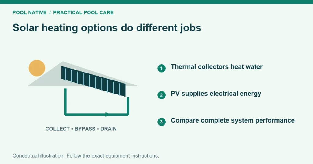
A typical pool solar thermal system circulates filtered pool water through collectors. The collectors absorb solar energy and transfer part of it to the water. The warmed water then rejoins the return route to the pool.
These collectors are different from photovoltaic panels, which produce electricity. A heat pump powered partly by rooftop electricity is another arrangement. It has its own electrical supply, controls and heating performance.
A bubble cover is different again. Its useful role includes reducing evaporation and heat loss from the pool surface. It does not replace a circulating collector array, although both can be part of the same heating plan.
The components and their jobs
| Component | Job in the system | What to keep in the equipment record |
|---|---|---|
| Pool rated collectors | Transfer absorbed solar heat into circulating water | Manufacturer, model, area and bank layout |
| Pump and filter | Supply filtered water at the required flow | Solar program and verified operating conditions |
| Diverter and bypass route | Select collector flow or ordinary return flow | Labeled normal positions and controller assignment |
| Temperature sensors and controller | Determine when solar heating is useful and wanted | Sensor locations, setpoint and operating mode |
| Check valves | Control reverse flow at specified locations | Direction and purpose of each valve |
| Vacuum relief and drainage provisions | Admit air and let the system drain as designed | Drainage method and seasonal instructions |
| Optional backup heater | Add heat when selected by the controls | Priority, permissions and sequence |
Use the solar pool heater plumbing diagram guide to follow the connections. A component list cannot reveal a trapped water pocket or a branch that receives too little flow. The installed route matters as much as the presence of each component.
What a normal heating day looks like
When the pool is below its target and usable solar energy is available, the controller can send water through the collectors. The circulation pump must run in the approved solar configuration. A manual system requires the corresponding owner action under its instructions.
As clouds arrive or the collectors cool, an automatic controller can stop the solar heating route. Once the pool reaches its target, heating can also stop. The pump may continue ordinary filtration through the bypass path.
Pump shutdown introduces another state: drainage. In a system designed to drain automatically, the collector and pipe layout must allow water to leave. A solar OFF indication does not prove that every pipe is empty.
Some controllers offer deliberate nighttime cooling. That is a separate chosen function, not evidence that every evening circulation period is useful heating. Check the selected mode if the pool seems to lose warmth while solar is active.
A hotter return does not necessarily mean more useful heat
Heat delivery depends on both water flow and its temperature rise. A small trickle can become quite warm while carrying less total heat than a larger flow with a modest rise. Touching a return cannot measure the system’s output.
For ordinary pool water, a useful approximate relationship is 500 × US gallons per minute × temperature rise in °F. The result is BTU per hour carried by that stream. It requires meaningful flow and temperature measurements at suitable locations.
As a calculated illustration, 40 gallons per minute warmed by 2°F carries about 40,000 BTU per hour. A 10 gallon flow warmed by 5°F carries about 25,000. The second stream feels warmer but carries less heat in this example.
These are hypothetical measurements, not performance claims for a product. Collector efficiency and pump energy also change with operating conditions. Do not throttle flow simply to produce a hotter outlet.
The installer should establish the manufacturer’s required flow through the array and its banks. Flow measurement and appropriate temperature observations can then distinguish weak collection from weak circulation. Neither measurement should require an owner to access a roof.
Design decisions that affect everyday operation
Collector area, seasonal sunlight, wind and the desired pool temperature interact. Usable roof area must allow for the actual collector layout and access. The solar heater suitability guide turns those questions into a selection checklist.
The pump must support the solar circuit without compromising other equipment. Long runs, undersized pipes and an unbalanced array can increase resistance or leave collectors poorly supplied. A suitable design considers both filling the array and normal circulation.
Multiple collector banks need balanced flow. One hot bank and one cooler bank can reflect different sun exposure, different flow or a measurement problem. Their temperatures alone do not identify the cause.
Roof mounting must account for the structure, weather exposure, waterproofing and access for repairs. Manufacturer requirements and local rules govern the installation. A roof that needs replacement soon changes the practical cost of the project.
Get a commissioning record, not just an ON demonstration
At handover, ask the installer to demonstrate ordinary filtration, solar heating and shutdown. Have each visible valve labeled by function. Record how the controller indicates a heat request and how it indicates solar is unavailable or satisfied.
The record should identify the normal solar pump program and any feature combinations that are restricted. Include the method used to confirm array flow and balance. Note the outdoor conditions during that check.
Ask how complete drainage was verified and what the owner must do before freezing weather. Obtain instructions for loss of power, service isolation and seasonal shutdown. Keep those with the exact collector and controller manuals.
If a backup heater is installed, confirm which source has priority and when backup is allowed. Verify the actual pool or spa body being heated. A control screen showing “solar preferred” needs an explanation of how that setting behaves when solar cannot meet demand.
Maintenance owners can organize from ground level
Inspect visible equipment and roof areas from a safe position. Look for new drips, stains, loose visible supports or a pipe that has shifted. Compare conditions before and during normal solar operation without walking on the roof.
Keep accessible baskets and the pool filter maintained under their own instructions. Retain pressure observations at the same operating speed. A circulation restriction can affect solar performance even when the collectors are undamaged.
Check that the controller’s pool temperature is plausible and the desired heating mode remains selected. Note any unexplained sensor warning, actuator movement or changed schedule. Don’t calibrate sensors merely to force agreement with a single thermometer reading.
Arrange the inspection and seasonal service required by the manufacturer and your installation. “Low maintenance” does not mean no inspection, no drainage check or no eventual valve and seal service. Access needs should have been part of the original plan.
Troubleshooting by the observed change
| Observation | Owner evidence to collect | Next investigation |
|---|---|---|
| Solar requested but valve does not move | Controller state and visible actuator behavior | Actuator power, setup or valve condition |
| Brief bubbles after normal startup | Duration and whether they stop | Compare with documented normal filling behavior |
| Persistent bubbles only with solar active | Pump prime, filter baseline and timing | Air entry, vacuum relief condition or inadequate solar flow |
| Pool warms less despite similar weather | Heating hours, cover use, valve mode and temperature record | Heat retention, collector flow, controls and array condition |
| New water appears during solar operation | Location, start time and whether it stops when solar is off | Collector, connection or pipe leak |
| Solar keeps running with no heat wanted | Setpoint, sensor readings and chosen mode | Control setup or sensor diagnosis |
A comparison with solar off can help localize an observation, but it does not prove the exact failed component. A leaking check valve or trapped water can keep feeding part of a bypassed system. Service isolation needs the documented procedure.
The valve actuator guide explains switching problems at the equipment pad. Do not force a drive, remove energized covers or cap a vacuum relief valve to stop bubbles. The pressure and drainage conditions must be corrected instead.
Freeze protection must match the whole installation
Water trapped in collectors, low pipe sections or isolated branches can freeze. Automatic drainage depends on the actual route and functioning components. Adding a vacuum relief valve cannot make water climb out of a trapped low point.
Follow the collector and controller manuals together. Some installations require manual drains or additional seasonal measures. Do not assume a circulation based protection mode works during a power failure or prolonged freeze.
An old manual or sales page may describe warranty terms differently from current documentation. Verify the terms for the actual product and installation rather than assuming freeze damage is covered. The practical goal remains preventing trapped water from freezing.
Judge performance against the intended season
Keep a simple record of starting and ending pool temperatures, weather, solar operating hours and cover use. Compare similar days and conditions. A single cloudy day cannot establish a failed system or its annual economics.
When expectations are not met, revisit the agreed temperature and swimming months first. Then check whether the system is collecting, delivering and retaining heat as designed. That sequence separates a repair problem from an installation that was never sized for the requested season.